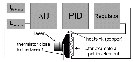
The reason to contruct a pid-regulator was to control the temperature of a laser diode. The laser diode I used for measurements during my phd-project had a temperature coefficient of about 0.3 nm/K. This means that the laser wavelength would increase by 0.3 nm if the temperature is increased by 1 K. Temperature dependent change in wavelebgth wasn't acceptable for my measurements. I not important here to describe the physical problems in detail. I only want to give a description of this regulator for somebody who has the same or a similar problem.
As sensor a thermistor was used. This is an ohmic resistor which resistivity is strongly temperature dependent. This resistor operates with a constant current (current source). If the temperaure of the thermistor changes the resistivity changes and there the voltage drop across the thermistor changes: U = I*R (Ohms Law). This means that temperature changes are converted into voltage changes.
The voltage drop across the resistor will be compared with a const reference voltage. The difference
between both voltage isn't zero the regulator 'acts' to bring the difference back to zero. The
schematic of the regulator should be clear now, see the figure.

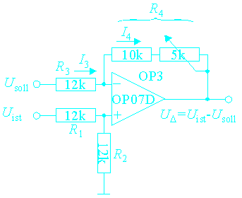
Because both inputs are voltages you have to determine the difference of these two voltages. I very easy way to do this is shown in the following figure.

In the following it is assumed that all resistors are equal. The voltage at the non-inverting input of the amplifier is U+ = R2/(R1 + R2) * Uist = Uist/2. The current through the resistor R3 is I3 = (Usoll - U+)/R3. The current through the resistor R4 can be calculated in a similar way: I4 = (UD - U+)/R4 where UD is the output voltage of the amplifier. Because no current flow into the ampifier the following equation yields: I3 + I4 = 0. With R3 = R4 you get the equation 2U+ = Usoll + UD. With U+ calculated above the output voltage of the amplifier finally becomes UD = Uist - Usoll.
The circuit of the main part of the PID-regulator in shown in the next figure. The two voltage followers OP1 and OP2 avoids any stress form the thermistor and the reference voltage supply, respectively. The next amplifier OP3 evaluate the difference of the tow input voltages, as described above. The jumper is useful to adjust the substracting circuit. If the jumper is set both input voltages are equal and the output voltage of the amplifier OP3 can be set to zero by adjusting the 5 kOhm-potentiometer (part of R4). After the zeroadjust the jumper must set back so that output the amplifier OP2 is connected with the inverting input of OP3 as shown in the figure.
The voltage UD would be applied to the three components labeled P, I and D, see the
following table. Unfortunately the formating capabilies of HTML are quite poor, so for a better view
click here.
| component | description | output voltage |
| P | prop. amplifier | Up(t) = - RP2/RP1 * UD(t) |
| I | integrator | Up(t) = - 1/RICI * INTt0tUD(t')dt' |
| D | differentiator | Up(t) = - 1/RDCD * dUD(t)/dt |
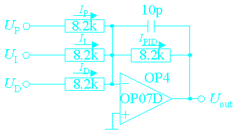
The three output voltages will be add by the next amplifier. No current flow into the amplifier so IP + II + ID + IPID = 0. Multiplication wuth R (= 8.2kOhm) yields: UP + UI + UD + UPID = 0. In principle the 10 p capactitor isn't necessary. The reason is that the voltage across the thermistor coudn't contain high frequency components because the system is thermally sluggish.
The next figure shows the circuit which add the signals from the P-, I and the D-component. In the following ignore the 10 p capacitor.

The working principle is very simple. Assuming that in current flowing into the amplifier is nearly zero, the sum of current through the resistors RP, RI and RD must be equal the current through the resistor Rf (f stands for 'feedback'). For RP = RI = RD = Rf = R the current equation can be written as: IP*R + II*R + ID*R = - IPID*R. Because of Ohms Law U = I*R you can also write: UP + UI + UD = - Uout.